
It’s the most sophisticated combustion system of solid products for the heavy clay industry existing worldwide on the market. It is the only installation which not only is similar to the most advanced gas combustion systems but it is the only system that is able to give a perfect adjustment in the working area of each burner. Moreover, this system beyond a perfect adjustment of coal / air ratio of each feeding pipe, it is able to offer a perfect adjustment of the coal-air mixture quantity of each feeding pipe.
There is no other system which manages to define and control the level of particle size of the solid fuel (it is well known that a smaller particle size ensures a better and immediate combustion), the temperature inside the kiln with regard to each burner, the flow rate of the air / coal mixture of each feeding pipe, the ratio of coal / air of each feeding pipe. The installation consists of two machines groups:
- Grinding group with controlled particle size and silage
- Combustion group on the kiln (CarboJet, TURBOJET)
E’ il più sofisticato sistema di combustione di prodotti solidi per l’industria dei laterizi, esistente sul mercato mondiale. E’ l’unico impianto che non solo si avvicina ai più avanzati sistemi di combustione a gas ma è l’unico sistema che riesce a dare una regolazione perfetta nella zona servita da ogni bruciatore e oltre ad una regolazione perfetta del rapporto carbone/aria relativamente ad ogni canna di alimentazione, riesce a dare una regolazione perfetta della quantità della miscela carbone-aria relativamente ad ogni canna di alimentazione.
Nessun altro sistema riesce infatti a definire e controllare il livello di granulometria del combustibile solido (è noto come una minore granulometria garantisca una migliore combustione immediata), la temperatura all’interno del forno relativamente ad ogni bruciatore, la portata della miscela aria/carbone relativamente ad ogni canna di alimentazione, il rapporto carbone/aria relativamente ad ogni canna di alimentazione. L’impianto consta di due gruppi di macchine:
-
Gruppo macinazione a granulometria controllata ed insilamento
- Gruppo di combustione sul forno ( CARBOJET, TURBOJET )
SBAS (SOLID BURNING ALPINA SYSTEM) is the only system that allows as a whole one:
- Definition and perfect control of the set particle size of Pet Coke dust
- Weekly deposit of Pet Coke dust
- Temperature control in relation to each burner
- Control and regulation of air transport and combustion
- Perfect regulation for each feeding pipe of fuel / air mixture ratio
- Perfect regulation for each feeding pipe of fuel / air mixture flow
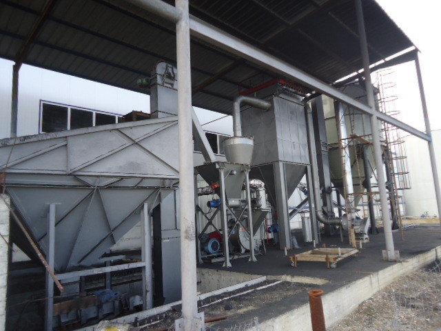
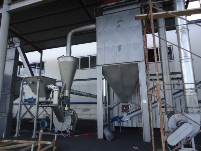
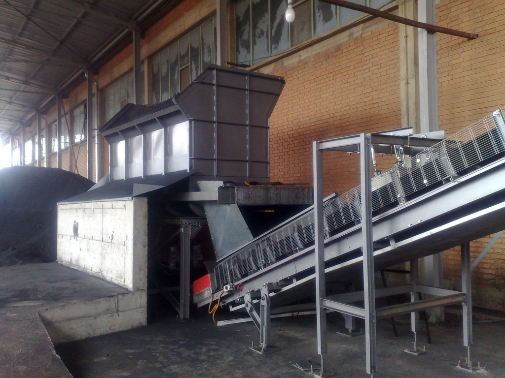
The installation in CarboJet System and Electrojet System versions, is composed of: coal or the Pet Coke grinding and ensiling group, an augers transportation system of micronized product, a dust silage system, and finally the proper combustion installation consisting of a series of burners with electronic control.
The special configuration of the grinding system, with the use of a special static or dynamic separator depending on the needs, of a sleeve filter and the air extraction fan to transport the dust through the filter, allows a perfect dosage of particle size range. An inverter responsible for the rotation of the fan ensures in fact a variation of the depression along the separator with the consequent variation of the particle size, so as to adapt it to the needs of the combustion.
The transport of dust, from the collection tank below the filter, by means of the augers of the mechanical type eliminates any leakage of coal dust in the external environment since it is the system which operates at the environmental pressure.
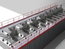
The real combustion system consists of a series of CarboJet or Electrojet type burners, it guarantees a perfect combustion with a control of each area of air / coal mixture and a local control of the temperatures inside the kiln by means of the thermocouples used by each burner.
Although it is not essential, however, it is useful to install in the first four rows of the firing openings on the kiln ceiling two heavy oil gasification groups, or gas self-ignition.
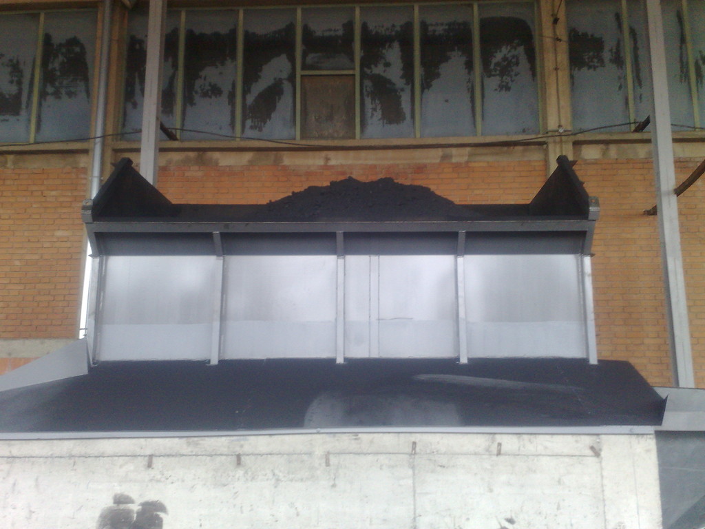
Pet coke is taken from the indoor deposit through the use of a loader which provides to load a feeding box with three augers of a special shape to convey the fuel towards the grinding system itself.
The feeding box is in fact equipped with vertical wall hoppers and three extraction augers at the base, to unload Pet Coke. The profile of the vertical wall hopper and the set of three augers at the base were designed to prevent the formation of any ’’bridge’’ on the mass of the solid fuel.
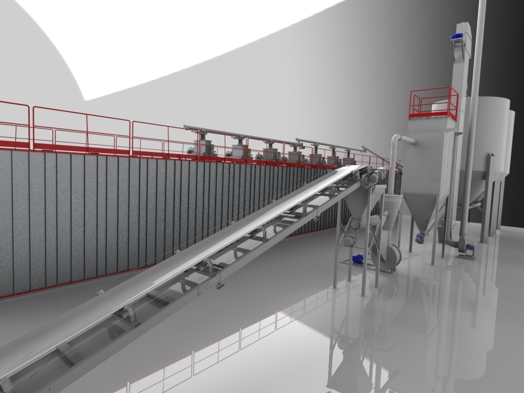
Pet coke is conveyed towards an auger transferring system or a rubber belt transferring system. Should there be any large distances, auger transferring systems can be used otherwise the rubber belts may be used as well. The metals detection system is inserted above the conveyor belt so as to avoid the accidental conveying of metal towards the hammer mill.
Pet coke will be unloaded from the conveyor belt into the batching box whose main task is to ensure a uniform and smooth feeding to the mill through the large auger at the base of the batching box itself. The batching box equipped with level indicator, receives the coke from the feeding belt or from an auger for its conveying towards the mill through a rotary valve.
The mill receives the fuel in variable size normally not exceeding 25 mm with the moisture less than 10%, mixed with the return residual after the grinding (whose particle size is higher than the maximum size set) together with a flow of hot air that will be then the transportation vehicle for the dust coming out from the mill.
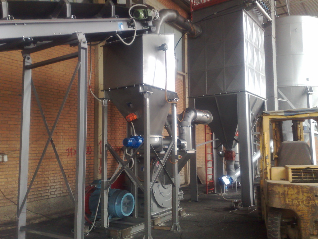
The machine is designed in order to receive hot air from the kiln recovery or from the other subsidiary source; the air has the dual task to eliminate possible pet coke deposit on the walls of the machine itself due to the humidity of Pet coke so that the mill can work properly and be fully efficient and to transport the coke dust to the static separator and finally, towards the sleeve filter. The entrance of the air and its flow towards the sleeve filter is secured by a high head fan placed over the filter.
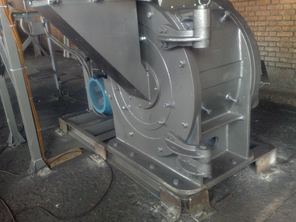
The hammer mill type is equipped with a central rotor on which swinging hammers on pivots are fixed, and with a notched casing getting the impact of the solid material. In the upper part an opening allows the exit of dust for depression towards the separator.
The movement of the coal after the mill is secured by air flow produced by the high pressure fan after the filter. The completely dried dust coal during its transport is conveyed into the separator where the separation takes place of the fine part from the coarse part which returns into the cycle. So being then stopped by the filter, it falls into the lower part of the filter itself where through a rotary valve it is conveyed towards the auger and the bucket elevator will lead it into the silo.
he greater or lesser opening of the separator fins, as well as the variation of the depression in the separator, allows a perfect dosage of the particle size range required depending on the type of the used solid fuel.
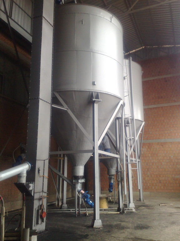
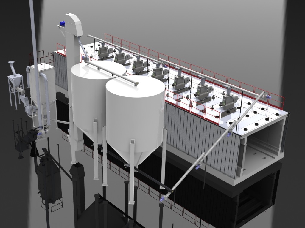
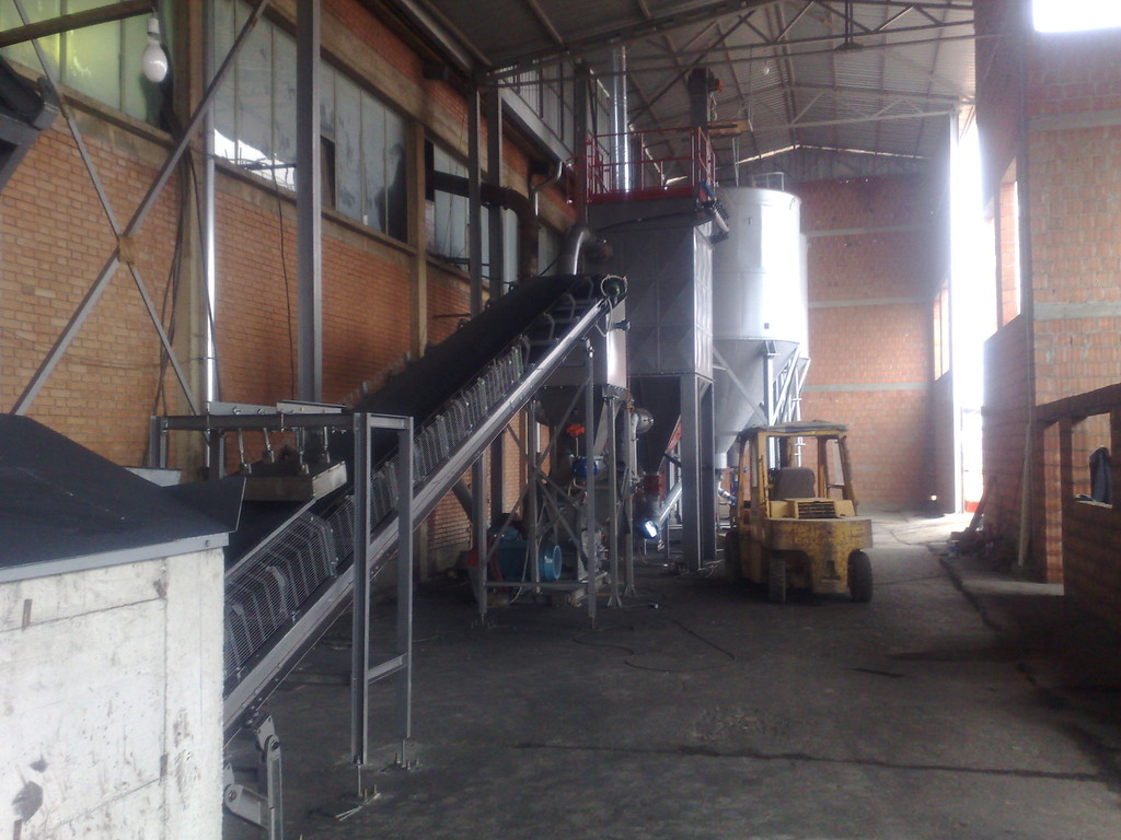
A bucket elevator carries the dust pet coke to two deposits with an equivalent capacity to 5-day reserve. The filter works “under depression”; the dusty air is sucked by the centrifugal fan, placed downstream of the system, which creates the necessary depression to win both the load losses of the circuit, and those caused by the resistance of the filters, once they reach the speed.
The filter needs a few days to reach the speed to give the maximum efficiency after a limited accumulation of dust (cake) is formed on the filtering device, which functions as a pre-filter.
herefore, it is not appropriate to do any instrumental detections of residual dust in the chimney, immediately after the start up. The dusty air sucked by the fan enters into the decantation chamber where by means of gravity the speed input slows down and the coarse particles are separated from finer ones for the first time.
The sleeves are arranged vertically in the filter chamber and the air blows into them from the outside to the inside. The air loses its dust content which is deposited on the outer surface of the filtering sleeves. The air on its way gets into the “clean chamber” through the hole where the venturi ejector type is placed. From here the filtered air exits from the filter housing, it goes through the fan and it is exhausted into the atmosphere through the chimney.
The cleaning system “reverse pulse jet” occurs in reverse current by means of jets of compressed air blown into the sleeves row after row, in a cycle, according to the program set on the included electronic sequencer. The compressed air is blown into the venturi ejector which has each sleeve. The pressure wave caused by the brief, but intense, compressed air mechanically deforms the surface of the sleeve. The shock wave leads to the detachment of the powder deposited on the outer side of the cartridge. Since the cleaning takes place during the normal operation of the intake system, the part of the detached dust thanks to the ‘”Venturi effect”, is again regained on the sleeve by the fan. It is necessary to effect “after-cleaning”, allowing the “reverse pulse jet” system to continue to work for a short period, even after the centrifugal fan stops its operation. The absence of suction facilitates the cleaning of the sleeves and the dust detaches from them almost completely and falls into the hopper. The time required for “after-cleaning” is measured according to the nature of the dust, to their particle size and concentration. Sophisticated electronic sequencers govern the operations of cleaning, during and after the operation of the suction system, controlling: the “?p” value, the programmed operation of the cleaning system and of “after-cleaning” and the detector of dust leak: finally, the possible leaks of dust are in the end reported identifying the row where the sleeve is cracked.
The filtered and separated dusts from the air are collected in a suitable metal container placed at the base of the filtering system and they are conveyed outside by means of a rotary valve or an auger.
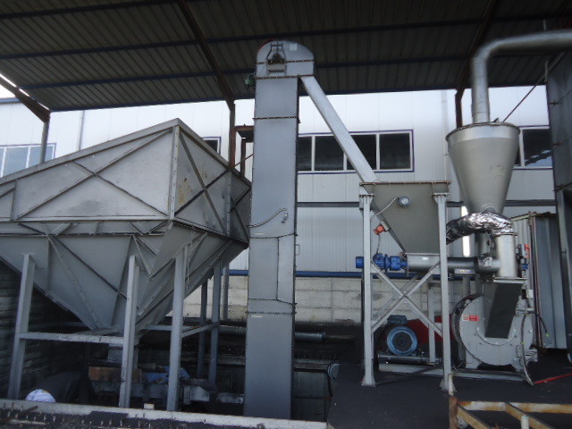
The coal dust at the exit from the metal container placed at the base of the filter is conveyed to a bucket elevator that provides watertight transport of dust to the storage silo. As it can be seen, the only pneumatic transport of dust in the whole installation happens from the mill to the filter. And such a transport takes place in depression, consequently there is a minimum dispersion of dust outside of the ducts.
Starting from the filter, the transport as a whole takes place in a mechanical way with the use of bucket elevators or augers.
WHY TO BID ON A PUSH AND CONTROLLED TYPE SPRAYING
During the combustion not all air is in contact with the surface of the fuel, so the combustion takes place in excess air, ie in the presence of an amount of air greater than the one stoichiometrically required. Considering that the excess air absorbs a part of the combustion heat, it is tried to reduce an excess air to the necessary minimum, which means you try to be as close as possible to the theoretical air.
In fact, using the theoretical air, the maximum combustion temperature is achieved, which means the maximum thermodynamic efficiency of the thermal cycle.
The theoretical air depends on the nature of the relative fuel, and it is a theoretical lower limit to the amount of air actually required for the complete combustion, since the efficiency is generally not equal to 100%.
The excess air is usually zero in the presence of gaseous fuels, where the mixing between the air and the fuel happens at a molecular level, whereas salt with liquid fuels or solid dust fuels nebulized in a very fine way, to reach highly elevated values in case of solid fuels with large size. This explains how the research of a push and controlled type spraying is constant in time to guarantee the thermal output. In order to accelerate the burning a turbulence is used, which increases the mixing between fuel and comburant, speeding up the combustion.
